In these blog we are going to learn that how to build an arduino dual motor shield and how we can decode and used the infrared remote.

Step 1: Parts and assembly!

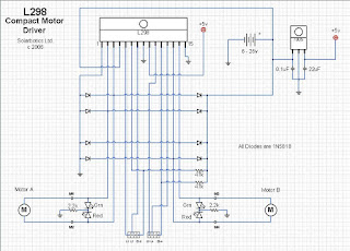

Parts:
- L298 Motor Driver (x1)
- Vero board (x1)
- Male or female Header Strip (enough to fit your arduino (32))
- 1N4007 Diodes (x8)
- 0.1uf and a 22uf capacitor
- Block connectors (x3)
- Jumper Wires
NOTE:
+5V connected to the E1-2 & E2-3 and these pins are enable pins so we are not connected to the block connector in these we need to add servo for steering and need enough PWM pins.
In these blog we are going to use the Red,Green LED’s and 2.2KHM resistor and counted on the serial communication.
Assembly:-
You can etch a circuit board and we are going to use the jumper wires.
In this blog firstly you can cut them so that it can be match your arduino pins if we are not using all pins then its is better to fit the headers on all of them so its looking very nice and stable.
then place the headers like you would any component and solder from beneath.
L1 and L2 are connected to Arduino pins 5 and 6 respectively which control motor (A) on pins 2,3 of l298 (forwards and backwards).
L3 and L4 are connected to Arduino pins 9 and 10 respectively .which control motor (B)on pins 13,14 of l298(forwards and backwards).
Step 2: Decode an IR remote.

In this blog the most important part is IR receiver.
You could either buy it or salvage it from and remote controlled device.
Pin1 of IR receiver goes to pin 11 of arduino , pin2 to ground ,pin 3 to +5v.
That’s everything for the hardware, now upload the attached file "IR-Decoder" to you arduino and open serial and make sure the baud rate is 9600.
Now get a remote and start clicking you should start getting values on the screen.
You need 2 buttons for the forwards direction(increase and decrease speed), 2 buttons for the backwards direction(increase and decrease speed),and 1 button for stop.
You choose whatever buttons you need .
NOTE:
Some of you may have noticed that if you press the same button for a long duration you'll get a different value which won’t work in the code, so you have to click the button gradually not continuously.
I found a lot of TV remotes that give you the same values while pressed for a long duration(example: Sony),you just need to keep testing remotes.
The code will work fine even if you don't find one but its better and faster this way.
#include <IRremote.h>
int RECV_PIN = 11;
IRrecv irrecv(RECV_PIN);
decode_results results;
void setup()
{
Serial.begin(9600);
irrecv.enableIRIn(); // Start the receiver
}
void loop() {
if (irrecv.decode(&results)) {
Serial.println(results.value, HEX);
irrecv.resume(); // Receive the next value
}
delay(100);
}
Step 3: Updating and uploading the code.
Now we're done with the IR-Decode file,we don't need it anymore,we only need the values that we noted.
now take these values and place them here but in the code(attached file):
#define upi 0x"value" ...(up increase)
#define upd 0x"value"... (up decrease)
#define Stop 0x"value" ...(stop)
#define downi 0x"value" ...(down increase)
#define downd 0x"value" ..(down decrease)
replace the ones in the quotes " replace" .
If your decoding and you get letters and numbers at the same time you have to place a 0x at the beginning, if you only have numbers don't place it.
So now connect everything up, place the shield on the arduino solder the IR Receiver pins as described before on the shield, connect the USB, and upload only the motor-shield-dual-motor-variable-speed file which you modified.
And after uploading open Serial and check if you’re getting feedback and attach one motor at a time because the arduino alone can’t handle two motors so it starts glitching.
After checking everything remove the USB cable connect an external power supply (12-18vdc)
and test both motors at the same time .
Note:-
if your motors aren’t rotating in the same direction and you dont want to flip the pins on the arduino or change the pins in the code just reverse the polarity of the motor
UPDATE:
I updated the code so that if you’re going forwards and u suddenly went backwards without stopping I’ll momentarily stop and start reversing and no matter how many times you pressed forwards and backwards without stopping you'll start from initial value or speed 0.
#include <IRremote.h>
#define upi 0x10FED22D
#define upd 0x10FE50AF
#define Stop 0x10FEB04F
#define downi 0x10FE30CF
#define downd 0x10FE926D
int RECV_PIN = 11;
IRrecv irrecv(RECV_PIN);
decode_results results;
int outPin1 = 9;
int outPin2 = 10;
int outPin3 = 5;
int outPin4 = 6;
int i=0,j=0,a=0,b=0,c=0,d=0;
void setup()
{
Serial.begin(9600);
pinMode(outPin1, OUTPUT);
pinMode(outPin2, OUTPUT);
pinMode(outPin3, OUTPUT);
pinMode(outPin4, OUTPUT);
irrecv.enableIRIn();
}
void loop()
{
if (irrecv.decode(&results))
{
irrecv.resume();
if(results.value== upi){
delay(30);
if(a>=1){
i+=5;
}
Serial.println(i);
digitalWrite(outPin2, LOW);
digitalWrite(outPin4, LOW);
Serial.println("increase speed forwards");
a++;
if(i>250){
i=250;
}
if(j<=250 && j>=0){
j=0;
c=0;
}
analogWrite(outPin1,i);
delay(100);
analogWrite(outPin3,i);
}
if(results.value== upd){
delay(30);
Serial.println(i);
if(b>=1){
i-=5;
}
digitalWrite(outPin2, LOW);
digitalWrite(outPin4, LOW);
Serial.println("decrease speed forwards");
b++;
if(i<0 ){
i=0;
}
analogWrite(outPin1,i);
delay(100);
analogWrite(outPin3,i);
}
if(results.value== downi){
delay(30);
if(c>=1){
j+=5;
}
Serial.println(j);
digitalWrite(outPin1, LOW);
digitalWrite(outPin3, LOW);
Serial.println("increase speed backwards");
c++;
if(j>250){
j=250;
}
if(i<=250 && i>=0){
i=0;
a=0;
}
analogWrite(outPin2,j);
delay(100);
analogWrite(outPin4,j);
}
if(results.value== downd){
delay(30);
Serial.println(j);
if(d>=1){
j-=5;
}
digitalWrite(outPin1, LOW);
digitalWrite(outPin3, LOW);
Serial.println("decrease speed backwards");
d++;
if(j<0){
j=0;
}
analogWrite(outPin2,j);
delay(100);
analogWrite(outPin4,j);
}
if(results.value== Stop){
delay(30);
i=0;
j=0;
digitalWrite(outPin1, LOW);
digitalWrite(outPin2,LOW);
digitalWrite(outPin3, LOW);
digitalWrite(outPin4,LOW);
Serial.println("Stop");
}
}
}
Step 4: update

If I get good feedback on this blog I’ll do a follow up that features a self navigating RC car with IR proximity sensors, and I’ll also share my Arduino code and explain how to modify it if you want to add more sensors for better navigation. Feel free to post comments and suggestions in the section below.


