Showing posts with label 12v. Show all posts

Monday, November 30, 2015

Remote Controlled Arduino Motor

In these blog we are going to learn that how to build an arduino dual motor shield and how we can decode and used the infrared remote.


Remote controlled Arduino motor

Step 1: Parts and assembly!

Remote controlled Arduino motor


Remote controlled Arduino motor


Remote controlled Arduino motor


Parts:


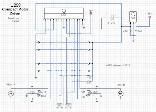
- L298 Motor Driver (x1)

- Vero board (x1)
- Male or female Header Strip (enough to fit your arduino (32)) 

- 1N4007 Diodes (x8)

- 0.1uf and a 22uf capacitor

- Block connectors (x3)

- Jumper Wires

NOTE: 

+5V connected to the E1-2 & E2-3 and these pins are enable pins so we are not connected to the block connector in these we need to add servo for steering and need enough PWM pins. 
In these blog we are going to use the Red,Green LED’s and 2.2KHM resistor and counted on the serial communication.

Assembly:-

You can etch a circuit board and we are going to use the jumper wires.
In this blog firstly you can cut them so that it can be match your arduino pins if we are not using all pins then its is better to fit the headers on all of them so its looking very nice and stable.

then place the headers like you would any component and solder from beneath.

L1 and L2 are connected to Arduino pins 5 and 6 respectively which control motor (A) on pins 2,3 of l298 (forwards and backwards).

L3 and L4 are connected to Arduino pins 9 and 10 respectively .which control motor (B)on pins 13,14 of l298(forwards and backwards).

Step 2: Decode an IR remote.

Remote controlled Arduino motor


In this blog the most important part is IR receiver.

You could either buy it or salvage it from and remote controlled device.

Pin1 of IR receiver goes to pin 11 of arduino , pin2 to ground ,pin 3 to +5v.

That’s everything for the hardware, now upload the attached file "IR-Decoder" to you arduino and open serial and make sure the baud rate is 9600.

Now get a remote and start clicking you should start getting values on the screen.

You need 2 buttons for the forwards direction(increase and decrease speed), 2 buttons for the backwards direction(increase and decrease speed),and 1 button for stop.

You choose whatever buttons you need .

NOTE: 
Some of you may have noticed that if you press the same button for a long duration you'll get a different value which won’t work in the code, so you have to click the button gradually not continuously.
I found a lot of TV remotes that give you the same values while pressed for a long duration(example: Sony),you just need to keep testing remotes.

The code will work fine even if you don't find one but its better and faster this way.


#include <IRremote.h>

int RECV_PIN = 11;

IRrecv irrecv(RECV_PIN);

decode_results results;

void setup()
{
  Serial.begin(9600);
  irrecv.enableIRIn(); // Start the receiver
}

void loop() {
  if (irrecv.decode(&results)) {
    Serial.println(results.value, HEX);
    irrecv.resume(); // Receive the next value
  }
  delay(100);
}

Step 3: Updating and uploading the code.

Now we're done with the IR-Decode file,we don't need it anymore,we only need the values that we noted.

now take these values and place them here but in the code(attached file):

#define upi 0x"value" ...(up increase)

#define upd 0x"value"... (up decrease)

#define Stop 0x"value" ...(stop)

#define downi 0x"value" ...(down increase)

#define downd 0x"value" ..(down decrease)

replace the ones in the quotes " replace" .

If your decoding and you get letters and numbers at the same time you have to place a 0x at the beginning, if you only have numbers don't place it. 

So now connect everything up, place the shield on the arduino solder the IR Receiver pins as described before on the shield, connect the USB, and upload only the motor-shield-dual-motor-variable-speed file which you modified.

And after uploading open Serial and check if you’re getting feedback and attach one motor at a time because the arduino alone can’t handle two motors so it starts glitching.

After checking everything remove the USB cable connect an external power supply (12-18vdc)

and test both motors at the same time .

Note:-

if your motors aren’t rotating in the same direction and you dont want to flip the pins on the arduino or change the pins in the code just reverse the polarity of the motor

UPDATE:

I updated the code so that if you’re going forwards and u suddenly went backwards without stopping I’ll momentarily stop and start reversing and no matter how many times you pressed forwards and backwards without stopping you'll start from initial value or speed 0.

#include <IRremote.h>
#define upi 0x10FED22D
#define upd 0x10FE50AF
#define Stop 0x10FEB04F
#define downi 0x10FE30CF
#define downd 0x10FE926D
int RECV_PIN = 11;
IRrecv irrecv(RECV_PIN);
decode_results results;
int outPin1 = 9;
int outPin2 = 10;
int outPin3 = 5;
int outPin4 = 6;
int i=0,j=0,a=0,b=0,c=0,d=0;
void setup()
{
Serial.begin(9600); 
pinMode(outPin1, OUTPUT);
pinMode(outPin2, OUTPUT);
pinMode(outPin3, OUTPUT);
pinMode(outPin4, OUTPUT);
irrecv.enableIRIn(); 
}
void loop()
{
if (irrecv.decode(&results))
{
irrecv.resume();
if(results.value== upi){
delay(30);
if(a>=1){
  i+=5;
   }
Serial.println(i);
digitalWrite(outPin2, LOW);
digitalWrite(outPin4, LOW);
Serial.println("increase speed forwards");
   a++;
if(i>250){
   i=250;
}
if(j<=250 && j>=0){
  j=0;
  c=0;
}
analogWrite(outPin1,i);
delay(100);
analogWrite(outPin3,i);
}
if(results.value== upd){
delay(30);
Serial.println(i);
if(b>=1){
  i-=5;
  }
digitalWrite(outPin2, LOW);
digitalWrite(outPin4, LOW);
Serial.println("decrease speed forwards");
   b++;
if(i<0 ){
   i=0;
}
analogWrite(outPin1,i);
delay(100);
analogWrite(outPin3,i);
}
if(results.value== downi){
delay(30);
if(c>=1){
   j+=5;
  }
Serial.println(j);
digitalWrite(outPin1, LOW);
digitalWrite(outPin3, LOW);
Serial.println("increase speed backwards");
   c++;
if(j>250){
   j=250;
}
if(i<=250 && i>=0){
  i=0;
  a=0;
}
analogWrite(outPin2,j);
delay(100);
analogWrite(outPin4,j);
}
if(results.value== downd){
delay(30);
Serial.println(j);
if(d>=1){
  j-=5;
  }
digitalWrite(outPin1, LOW);
digitalWrite(outPin3, LOW);
Serial.println("decrease speed backwards");
  d++;
if(j<0){
  j=0;
}
analogWrite(outPin2,j);
delay(100);
analogWrite(outPin4,j);
}
if(results.value== Stop){
delay(30);
  i=0;
  j=0;
digitalWrite(outPin1, LOW);
digitalWrite(outPin2,LOW);
digitalWrite(outPin3, LOW);
digitalWrite(outPin4,LOW);
Serial.println("Stop");
}
}
}

Step 4: update

Remote controlled Arduino motor


If I get good feedback on this blog I’ll do a follow up that features a self navigating RC car with IR proximity sensors, and I’ll also share my Arduino code and explain how to modify it if you want to add more sensors for better navigation. Feel free to post comments and suggestions in the section below.


Friday, November 27, 2015

Fire Alarm System GSM based using Arduino

You know that 90% fire damage occur due to the lack of early detection but now we are going to solve these problem. With the help of these technology we can reduce this problem. So in this system we can use a GSM module in which when fire occurred then the sms send to the users mobile no or you can replace the sms  with your own string.


GSM based Arduino

Components:-

  • Arduino Uno
  • LCD 16X2
  • LM35 Temp Sensor
  • GSM MODULE
  • 5v Power Supply for Arduino
  • 12v Power supply for GSM MODULE
  • 10k Potential Meter

Demo on Proteus:-

In this system we can set the threshold value in the code if (temp>45).when the temp reaches the 45 C then SMS send to the user mobile no. When fire occurred you can replace this value by your own but we know that very well that the room temp is 25 C. So when we are going to set the value we know that what the room temp. So we can change our value according to the room temp..
You can change the mobile no of a person with the cell phone no. to receive the fire alert SMS.  

GSM based Arduino
GSM based Arduino


Download the Code:-

In this system coding is very simple you can easily know about that. You cannot face any problem to make this project.
#include <SoftwareSerial.h>
#include<LiquidCrystal.h>
LiquidCrystal lcd(12, 11, 5, 4, 3, 2); 
SoftwareSerial mySerial(9, 10);
int sensor=A1;
float temp_read,Temp_alert_val,Temp_shut_val;
int sms_count=0,Fire_Set;
void setup()
{
  pinMode(sensor,INPUT);
  mySerial.begin(9600);   
  Serial.begin(9600);    
  lcd.begin(16,2);  
  delay(500);
}
void loop()
{
CheckFire();
CheckShutDown();
}
void CheckFire()
{
lcd.setCursor(0,0);
lcd.print("Fire Scan - ON");
Temp_alert_val=CheckTemp();
if(Temp_alert_val>45)
{
  Fire_Set=1; 
lcd.setCursor(0,1);
lcd.print("Fire Alert! SMS Sent!");
while(sms_count<3) //Number of SMS Alerts to be sent
{  
SendTextMessage(); // Function to send AT Commands to GSM module
}
}
}
float CheckTemp()
{
temp_read=analogRead(sensor); // reads the sensor output (Vout of LM35)
temp_read=temp_read*5;    // converts the sensor reading to temperature
temp_read=temp_read/10;  // adds the decimal point
return temp_read; // returns temperature value in degree celsius
}
void CheckShutDown()
{
if(Fire_Set==1)
{
Temp_shut_val=CheckTemp();
if(Temp_shut_val<28)
{
lcd.setCursor(0,1);
lcd.print("Fire Shut! SAFE NOW");
sms_count=0;
Fire_Set=0;
}}}
void SendTextMessage()
{
  mySerial.println("AT+CMGF=1");    //To send SMS in Text Mode
  delay(2000);
  mySerial.println("AT+CMGS=\"+929542xxxxxx\"\r"); // change to the phone number you using 
  delay(2000);
  mySerial.println("Fire in NEW ROOM!");//the content of the message
  delay(200);
  mySerial.println((char)26);//the stopping character
  delay(5000);
   mySerial.println("AT+CMGS=\"+929847xxxxxx\"\r"); // change to the phone number you using 
  delay(2000);
  mySerial.println("Fire in NEW ROOM!");//the content of the message
  delay(200);
  mySerial.println((char)26);//the message stopping character
  delay(5000);
  sms_count++;
}
So this was all, assemble your own alarm, test it and if you like the project, reflect it in the comments section below!!

Monday, November 23, 2015

Arduino Mini

I bought an Arduino Ethernet shield which is used for design the Arduino Nano. After that I thought that I could easily hook the Arduino Ethernet up to my Arduino nano but its can not be done so I feel I was wrong.

I have not much more information to this that how can its use but I have some knowledge about the IO pins.

I tried to hook up the all the matching wires with my Nano but it was not success.
After that I bought a proper Uno then I find in which 6 pin connector but its  not properly categorize and the 6 pin connector have not special shape its very simple so its can hook up very easily but in two ways.

After that I had to do little bit searching that what pin connecting to Nano nd what connected to shield, to make sure I could not be connecting backwards.

So facing these problems I thought that I would add this fast small instruct able so that any other would not face these problems again.

Then I am sure that I find the much more use for another Arduino.
Here we present a new instruct able that hook up an Arduino Nano with a smaller WIZ550io module.


arduino-mini


 Parts Of Arduino Nano

  •       1 ArduinoNano. (if you have already Arduino Uno, just plug it)
  • .    1 Ethernet shield with SD card slot, with Wiz net w5100 chip. The w5100 have lot of programming which is directly support the Arduino libraries.
  •       5 mm hookup wires.
  •      1 breadboard
  •        1 micro SD card
  • .     A couple of business cards or a piece of paper.


For software you will need the Arduino 1.0 software
The Nano is similar to the Uno but it is very small and has male header pins. Its is very wonderful for plugging into a board. You can buy the Ethernet shielded for the Nano but it is very expensive.

When you are going to buy the shield,you have to note the important point that some of the shield do not support the SD card.Here,I buy the shield which has SD card in it-that will not cost that much and it will be very beneficial for various other projects.
It also allows for much more advanced ethernet board examples!

When you are going the files in SD card you will find the many way to hook up into computer. To success this work we will need a micro to regular SD card adapter. I am using the SD to USB.


arduino-mini


Insert Arduino Nano into breadboard
We are using the Arduino Nano many times if we have interest in this. I joint my Nano at the right side of board so that the USB connect at the edge and this edge has two holes i.e. D12 & D13. It’s become very beneficial to use board at this time


 Plug ICSP of shield onto the Nano
We are going to make the connection but very carefully. At this time we can’t use the power in the board.

We can connect the shield in two ways firstly to cover the nano and other does not.we need to plug in the shield so that all nano make visible. This turns out well, as it gives full access to the Nano connections that way.

Also make sure that you get all 6 pins plugged in.
Because the shield's pins are all exposed underneath, I had some business cards underneath to ensure that the pins cann’t accidentally connect with the power bus.


arduino-mini


Connect the wires
Connecting the wires is easy - simply match up the label on the Arduino Nano with the same label on the ethernet shield. The ICSP connector does most of the work and hooks up the power, so we only need 5 wires to complete the setup:

Pins 11, 12, 13 (SPI bus)
Pin 10 selects the w5100
Pin 4 selects the SD card

arduino-mini

Test the setup

To test the setup, you can use the built in Arduino examples under the File-Examples menu list, under the Ethernet and the SD folders.

One thing that's a bit of a bother is that it only supports the old DOS style 8.3 filenames, not long file names.

We are going to test the Ethernet and the SD card at the same time.


Ladyada is the updated version and you can replace this outdated reference to server with Ethernet server and client with client server.


Wednesday, November 18, 2015

Arduino Uno R3


There are some problems in our country. One day me and my Friend discussd to this problems. In our streets there is little bit security because of social in equality. In or society no one is safe even not richer because the no of robbers are increase day by day they can get easily inside the homes. so we make  system for home security purpose. But this system is very expensive and in this system we use a ring alarm to scare the thieves. But they do not actually inform you in immediate time that your house is being secure. When this system being completed its very expensive.
So I have an idea to make my own ring alarm which based on arduino. For this purpose I bought a GSM shield for Arduino Uno and other part I had.


arduino-uno-r3


 Parts Of GSM shields Home Alarm
 For this project you will need:-
Arduino Uno (Robomart);
GSM Shield (Robomart);
PIR sensor (Robomart);
An Arduino based buzzer (Robomart);
An alarm siren horn 12V(Robomart);
12V power supply (Robomart);
Relay module (Robomart);
Keypad for the Arduino (Robomart);
A box;

 
arduino-uno-r3

 
arduino-uno-r3


How to make connections

Firstly we have to place the Arduino Uno below the GSM shielded, then we solder  the two wires to GND and VCC jointly from two sensors, the buzzer and relay module input. After that we can connect the two wires on the connecter from GSM shield. After that we make a connection from input/output signals to this parts. And the last remaining thing is that we connect shield below the keypad.

It will be:-


 ArduinoUno / GSM shield pins:

·         Pin 0: not connected
·         Pin 1: not connected
·         Pin 2: not connected (the GSM will use this pin)
·         Pin 3:  not connected (the GSM will use this pin)
·         Pin 4: last row from keypad (keypad pin 4 – from 8);
·         Pin 5: not connected;
·         Pin 6: second column from keypad (keypad pin 6 – from 8);
·         Pin 7: third column from keypad (keypad pin 7 – from 8);
·         Pin 8: not connected (the GSM will use this pin);
·         Pin 9: not connected (the GSM will use this pin);
·         Pin 10: PIR sensor number 2 data;
·         Pin 11: siren horn signal (goes to the relay module input);
·         Pin 12: PIR sensor number 1 data;
·         Pin 13: buzzer signal input;

As it is possible to see, although the keypad has 8 pins, I just connected three (one row and two columns, allowing two numbers to be read – 1×2 matrix), because this way I can make passwords using these three wires, and there is no need to use all the pins from the keypad. This is because once the movement sensor detects a person walking inside the room, the person will have just 5 seconds to deactivate the alarm, so there is not enough time for the thief to figure out the alarm code. Once the alarm is not disabled on the given time, the GSM shield will proceed to send SMS to you, or to call your phone. The Arduino was programmed to call and once you answer the phone, it will finish the call. This way it will spare the credits from the mobile operator.
Of course, it is possible to get false readings from the sensor, or even the code can be buggy, so I put an option to disable the alarm just by sending an SMS text from my phone to the Arduino. Then we can send a message to show that this system will be correct.

 Conclusion of this system

After 5 sec you get a message or call in your phone when any thieves enter in your house after you can call police because I think you have much time to call the police.
When you receive the message after that the siren horn will alert the thieves and they will run without taking whatever they can. But if we do not use the siren then the thieves will not alert and they can catch by police. So by this system we can make our hose very secure.
If you have much better idea please suggest me so that I can improve my systems. 
Now You Can Visit This Link:------
 https://www.youtube.com/watch?v=_hBNhjIuz8k 


Tuesday, November 17, 2015

ARDUINO BLUETOOTH CONTROL BY WINDOWS DEVICE

Its my first blog post that how can we manage arduino with Bluetooth. Its very fast apps that we are use in windows app store. I am using arduino Bluetooth bot you can use further module.
Windows: 8.1 & 10
I am using arduino Bluetooth bot you can use further module.


ARDUINO BLUETOOTH CONTROLLER PARTS


arduino-bluetooth-control-board


Arduino-bluetooth-control-board


Arduino-bluetooth-control-board


Arduino Sketch & Upload


int led = 13; 

void setup()
{
      Serial.begin(9600);
      Serial.flush();
      pinMode(led, OUTPUT);  
}


 void loop()
 {  
   String command = "";
  
      while (Serial.available() > 0)
    {
        command +=  Serial.readString();
       delay(5);
}

    if (command == "on")
    {
        digitalWrite(led, HIGH);
    }
    else if (command == "off")
     {
         digitalWrite(led, LOW);
     }
 }


 Assembling of the project


Arduino-bluetooth-control-board

We are assemble this project with the matching wires.
You can use shorter wires to remove difficulty.
-------------------------------------
-------------------------------------
Bluetooth = Arduino Pin
BLL VCC = 5v or Vin (USB only power arduinos)
BL GND = GND
BL Rx = TX pin
BL Tx = Rx pin
-------------------------------------
-------------------------------------
 Component = Arduino Pin
Led + = 13 pin
Led - = GND
.We can use arduino led in place of normal led.

Bluetooth Pair and Search

Arduino-bluetooth-control-board


 1.We can install very fast app from windows store and to install this we need windows 8.0 &10.

2. Pair your device to your laptop.
The initial pair only has to be done one time.
Most passcodes are 1234 or 0000.

 3.Open Quick Terminal and search for your device. 

How It Works:-

Arduino-bluetooth-control-board


 When we send ON command in circuit, then the Led will glow and when we send OFF command then our Led will turn off.
We can use different  type of command to control the more things in Bluetooth control Arduino.

You can also visit this link: